



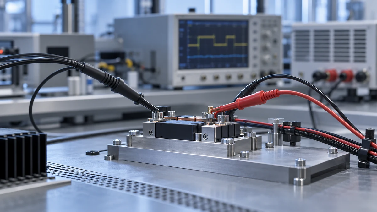
Wide-bandgap devices switch faster, which places greater demands on the measurement chain. Seeing a waveform on screen does not prove that it is trustworthy. Bandwidth, common-mode conditions and channel alignment are three separate limits to confirm.
Bandwidth and rise time
Bandwidth describes how much of a fast edge the chain can preserve, while rise time describes the step response more directly. Probe, current sensor, cable and acquisition front end all contribute; the weakest stage limits the result.
Also consider how the probe loads the circuit. Input capacitance, load resistance and grounding can change the switching behaviour itself, so the measured event may differ from the unloaded circuit.
Common-mode conditions
For differential voltage measurement, the differential quantity is only half of the problem. Fast movement of the switching node relative to ground is a common-mode condition, and the probe must maintain adequate rejection at the relevant frequency.
A DC or low-frequency common-mode rejection figure does not describe the switching instant. Check common-mode voltage, frequency and the probe’s rated limits together before trusting the measurement.
Channel alignment
Current and voltage channels have different propagation delays, and acquisition channels may be offset in time. For power analysis, measure or correct the inter-channel timing before discussing waveform detail; otherwise probe delay is mistaken for device behaviour.
Define the time scale of the switching event first, then check bandwidth, common mode and alignment in that order. This is closer to a reliable measurement than chasing maximum bandwidth alone.
Need to discuss a measurement setup?
Tell us the measurement target, range and existing equipment so we can review the chain for the actual task.
Continue reading
Technical documents
Matching Oscilloscope and Probe Interfaces
Technical documents