



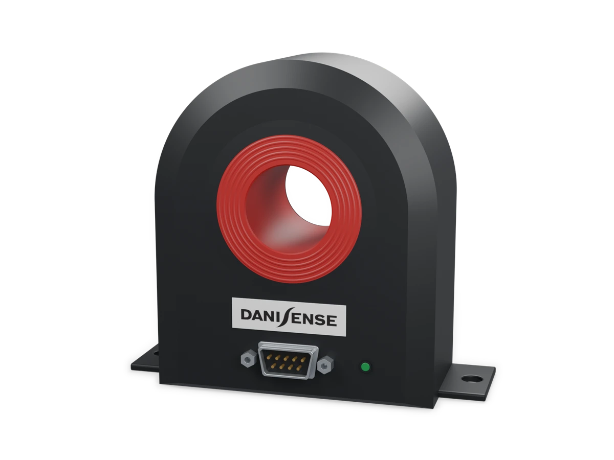
A zero-flux current sensor is often selected as a standalone precision device, but the reading depends on the whole measurement chain: how the sensor is powered, what load its output drives, and how the signal reaches the acquisition equipment all affect the final result. Checking the sensor, supply, output load and acquisition equipment together is closer to real use than comparing a single accuracy figure.
Define the measurement objective
Zero-flux current sensors support precision measurement within the limits specified for each model. Beyond rated range, consider DC offset, linearity, temperature variation and frequency response. One sensor specification cannot directly represent the result of the complete measurement system; the measurement conditions must also be stated.
Start with the form of the current: stable DC, DC with ripple, power-frequency AC, or pulse and transient events. Each places different demands on the chain. DC measurement places more weight on offset, drift and noise; AC measurement on frequency response and phase; pulse measurement also requires rise time, duration and recovery from overdrive.
Define two limits beyond the rated range: the smallest change that must be resolved and the largest current likely to occur. The first sets noise and resolution requirements; the second sets headroom and safety margin. Record the measurement duration, ambient temperature and installation space as well, so that the chain can be checked against real conditions.
Check the measurement chain
Check supply requirements, output type, load conditions and acquisition input range throughout the chain. Current outputs and voltage outputs have different interface requirements, and any required signal conditioning must match the documentation. Long-term recording also requires attention to environmental changes and repeatability so that product selection suits the actual test duration.
Power is the first item that is easily overlooked. Confirm the supply form, permitted ripple and isolation requirements, and check whether an unintended path exists between supply ground and acquisition ground. At the output, check the load resistance or burden, cable length and shielding. A current output is more sensitive to load and interference over long cables; use buffering or conditioning as specified where necessary.
At the acquisition end, check input impedance, range, common-mode limits and sample rate. Too wide a range sacrifices resolution for small signals; too narrow a range may clip. If common-mode conditions do not match, the acquisition input can add error even when the sensor output itself is correct.
Locate the error source in the chain
Offset affects readings near zero current, gain error affects the relationship between output and input, and temperature or time-related changes can alter both. The measurement system also includes the acquisition instrument and any necessary output conversion. When comparing data, record the definition and conditions of each specification; do not treat different types of error as the same accuracy figure.
Sort the error sources into three groups: the sensor’s own offset, gain, linearity and temperature drift; load, noise, grounding and shielding in transmission and conditioning; and quantization, bandwidth, timebase and common-mode rejection at the acquisition end. Recording each stage is more useful than attributing the whole chain’s deviation to one device.
Begin with a zero-current check, then apply a known reference current and compare the output with expectation. Where conditions allow, repeat near the working temperature and over the actual recording duration. This separates initial accuracy from long-term stability and shows whether a deviation is a fixed offset or changes with the environment.
Match output form and interface conditions
A current-output sensor and a voltage-output sensor cannot be judged compatible from connector appearance alone. Check rated output, permitted load, supply and acquisition input requirements; when a matching interface unit is used, also confirm the sensor models it supports. Any conversion or conditioning at the output becomes part of the measurement chain and belongs in the documentation review.
A current output can suit longer cables, but its permitted load range must be confirmed. A voltage output is easier to connect to an acquisition input, but output impedance, loading and ground loops still matter. In either case, connector appearance alone does not establish compatibility.
When a matching interface unit or conditioning module is used, confirm the sensor models, supply and output range it supports, and include the conversion stage in the error budget. Connectors, shields and grounding points should follow the documentation to avoid ground loops in electrically noisy environments.
Compare dynamic and stable performance for the recording goal
For long-term DC observation, drift, noise and environmental conditions deserve priority. If the goal includes AC or transient events, compare frequency response and overdrive conditions as well. A larger rated range is not necessarily better for small-current measurement; choose according to the actual working range and the change that must be resolved, and keep a complete record of the configuration.
For waveform observation, consider bandwidth, rise time, sample rate and the response of probes and cables together. For long-term recording, give priority to offset drift, noise density, temperature coefficient and repeatability. The trade-offs differ, and no single set of specifications covers every task.
Allow margin for overdrive and abnormal events. The current may briefly exceed the rated range, and recovery time, saturation behaviour and reset method can affect subsequent records. Comparing range, bandwidth and recording duration in one table makes the real limiting factor easier to see.
Record the configuration in a reviewable checklist
Once the selection is complete, record the actual configuration in a checklist that supports handover, repetition and troubleshooting:
- Model, serial number and calibration status of the sensor;
- Supply form, voltage or current, and grounding method;
- Output type, load resistance or interface unit, and cable length;
- Acquisition model, input range, sample rate and filter settings;
- Ambient temperature, installation position and warm-up time;
- Zero-current check result, reference point and date.
The checklist need not be long, but another engineer should be able to reproduce the measurement from it. If the sensor, cable or acquisition card is later changed, compare the new conditions with the checklist before deciding whether a difference comes from the device or from the chain.
The key to a zero-flux current measurement chain is not a single “best” device but the match between its parts. Define the task, check supply, loading, interface and acquisition conditions stage by stage, and fix the configuration in a checklist; selection and troubleshooting both become more reliable.
Related products
Need to discuss a measurement setup?
Tell us the measurement target, range and existing equipment so we can review the chain for the actual task.
Continue reading
Technical documents
Wide-Bandgap Switching Tests: Three Limits of the Measurement Chain
Technical documents