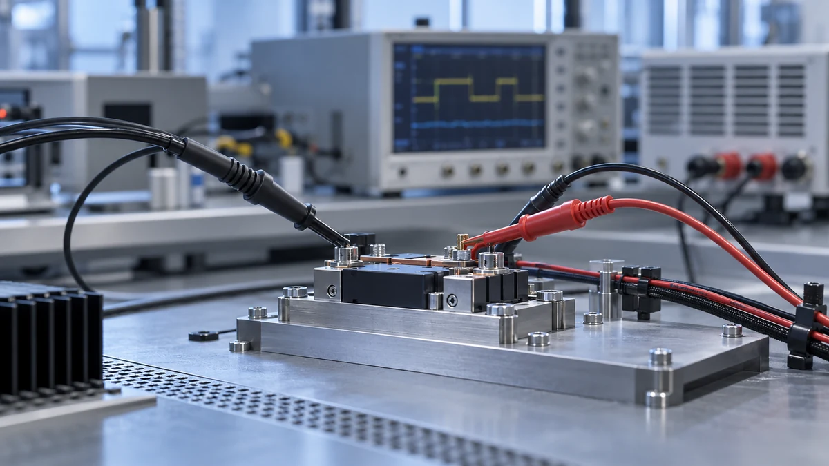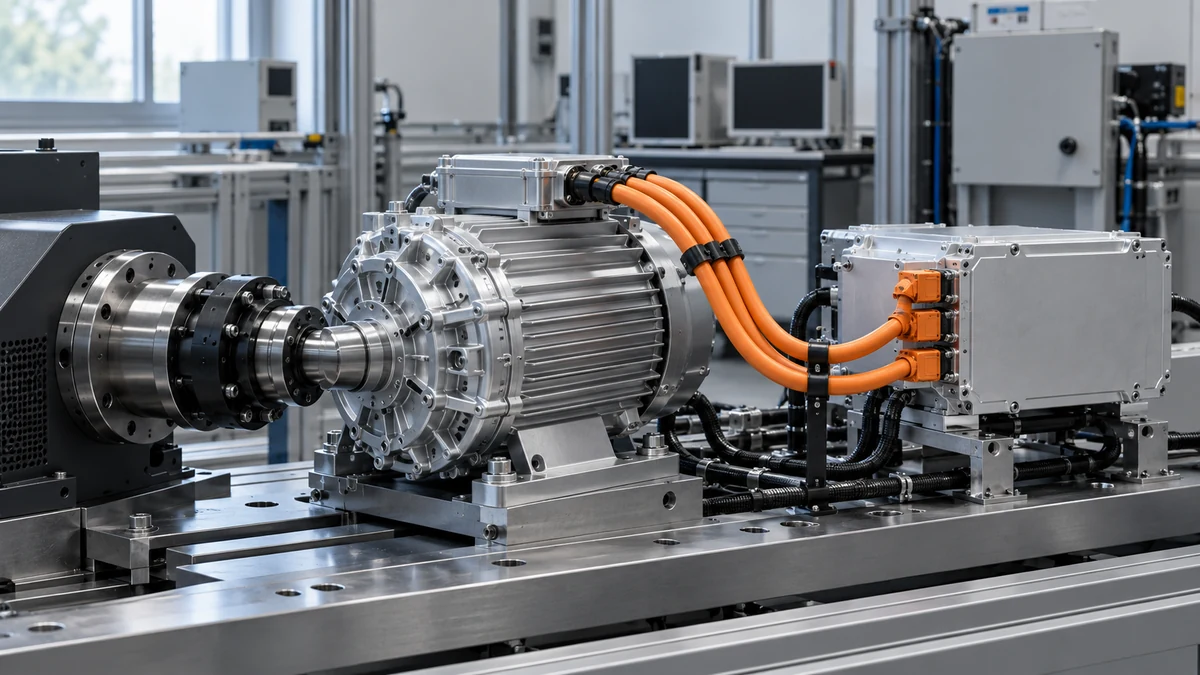
Electric drive testing often looks at phase current, DC-link voltage and switching waveforms at the same time. The three quantities come from different points and different probes, then need to be compared on one time axis, so range, bandwidth and synchronisation must be planned together.
Measuring points and ranges
Phase current can use a Rogowski coil or current probe, while DC-link voltage usually uses a differential probe. Leave headroom for starting, overload and switching spikes, but remember that an unnecessarily wide range sacrifices resolution for small signals.
Channel timing
Different probes have different propagation delays, and acquisition channels may be offset. Before efficiency or power analysis, confirm the inter-channel timing and decide whether deskew is needed. The sample rate should cover the switching frequency and edge of interest.
Recording and reproduction
Record speed, torque, DC-link voltage, ambient temperature and probe configuration together so later comparisons have context. Wiring and grounding on the bench belong in the record too, otherwise another engineer cannot reproduce the test.
Whether bench data is comparable often depends on these surrounding conditions rather than on the highest specification of a single probe.
Need to discuss a measurement setup?
Tell us the measurement target, range and existing equipment so we can review the chain for the actual task.