Measurement task
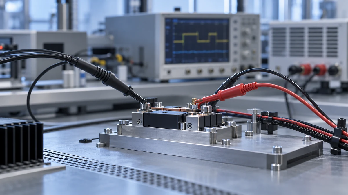
Power semiconductor testing often requires simultaneous observation of device voltage, current and switching timing. Measurement-point space, conductor shape and signal slew rate constrain probe format. First define whether the objective is waveform observation, comparison of switching behavior or loss analysis, then determine the required measurement channels.
Selection considerations
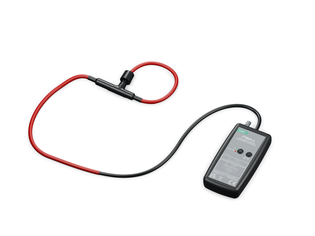
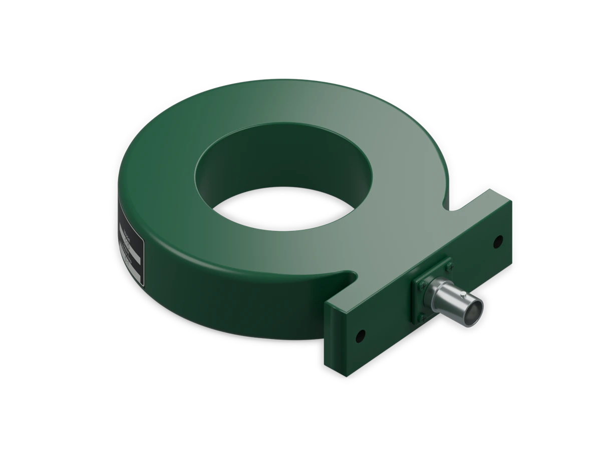
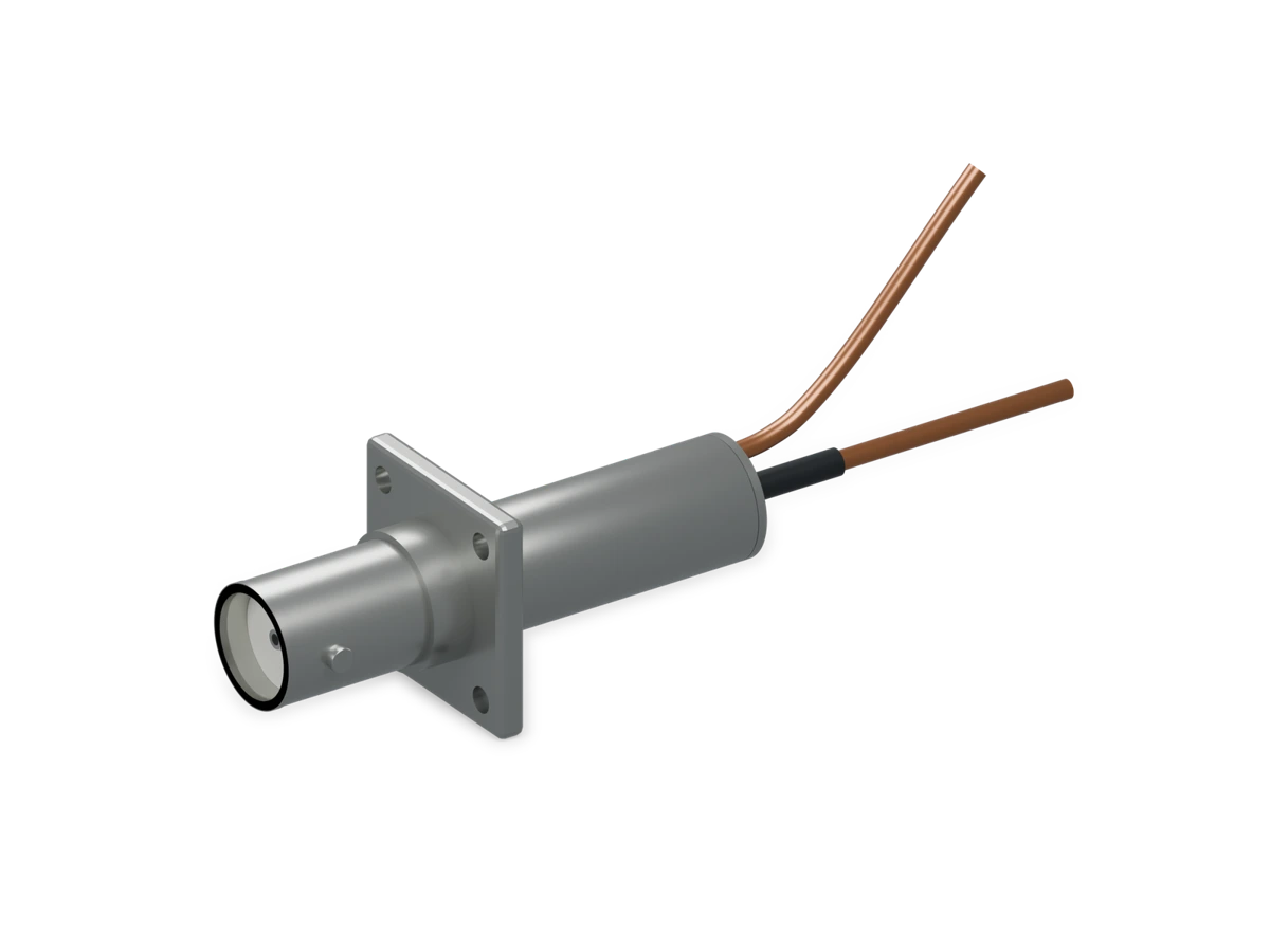
Consider bandwidth, probe loading, noise and channel delay together, rather than comparing a single maximum specification. Miniature Rogowski coils, pulse current transformers and shunts each have their own operating conditions. Voltage probes also require checks of differential range and common-mode conditions. The final assessment depends on model documentation and the complete measurement chain.
Device waveforms and measurement loading
During switching, the relative timing of voltage and current waveforms matters as much as their amplitudes. Probe loading, bandwidth and delay can affect the observed spikes or overlap intervals. A probe suitable for closely spaced device leads differs from one for a busbar. Check measurement-point space and permitted connection arrangements before judging whether a model meets signal requirements.